This is the history of the SG Radiant Oscillator and how things get stolen even when you have people you trust helping you.
Even if they signed a confidential disclosure you still can't trust them. And then people ask why I do not answer them.
Judge for yourself why you never have seen John talk about the oscillators.
However, Peter and I never said anything obout OU at all since we were just testing The Negsistor effect in the transistors oscillators.
On Tue, 1/19/10, Rick Friedrich <rickfriedrich@yahoo.com>
wrote:
From: Rick Friedrich rickfriedrich@yahoo.com
Subject: Fw: Some Pictures for you
To: john34@johnbedini.net
Date: Tuesday, January 19, 2010, 10:41 AM
--- On Wed, 10/12/05, Stan Mayer <stanmayer@cableone.net> wrote:
From: Stan Mayer <stanmayer@cableone.net>
Subject: Some Pictures for you
To: "Rick Friedrich" <rickfriedrich@yahoo.com>
Date: Wednesday, October 12, 2005, 5:18 PM
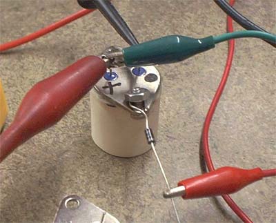
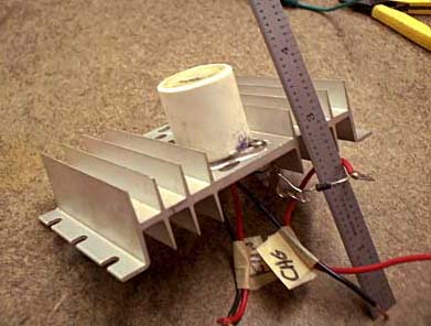
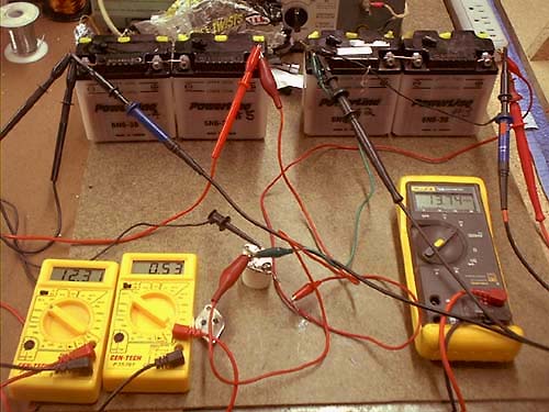
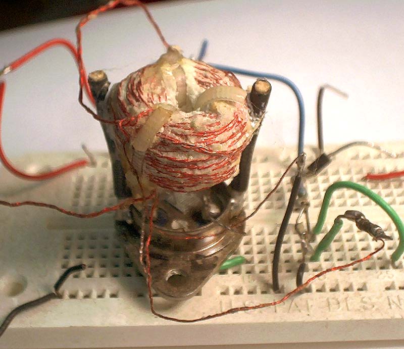
Rick, As promised here are some pictures of the "tube" oscillator that I received from John during my visit with him in November, 2004. John didn't tell me if the unit that he gave me was a working OU one or what so it could have been a prototype but I was darned happy to get it. As I told you during one of our phone conversations, I did some experiments with it, rotating small lead-acid motorcycle type batteries around it and while I found the oscillator to be a darned good charger with an efficiency of at least 80%, in the few test rotations that I did, I never saw any sign of OU and/or improving efficiency but at that time I was in a hurry to continue my motioned energizer experiments, utilizing the information just observed at John's lab so I temporarily(?) discontinued experiments with it. The picture below is of the basic device. Note that the + and dot marks on it were placed there by John. The diode ... a 1N4007 ... was included with the osc. given to me by John and in fact is shown exactly as it was attached to the tube osc. that John demonstrated to me.
Okay, Rick, .... from this point on, these pictures are ... how shall we say ... confidential. That is, as RS has seen them, you can of course discuss them with him but for now, no one else please. The reason that I request that you do this is that should John see the pictures of the dissected tube oscillator that he gave me, he might not be very happy about this.
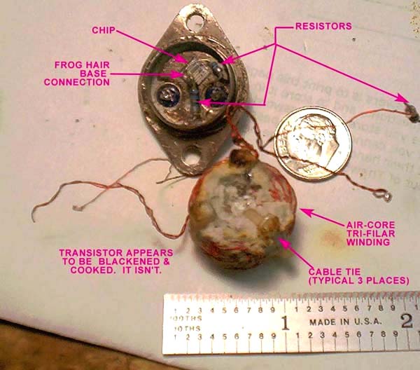
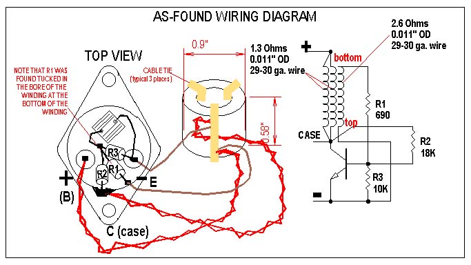
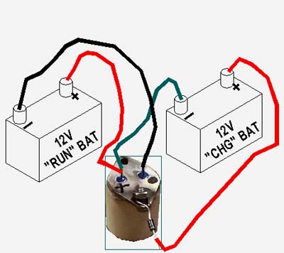
You will want to review the "As Found Wiring Diagram" carefully because in addition to a wiring diagram and schematic, it shows the physical dimensions and wire size of the winding which consists of three strands of #29-30 ga. wire twisted together of which two of these strands are for the main/drive winding and the remaining third strand is the trigger winding.
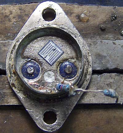
Additionally, my coexperimenter friend David J. and I did further research in an effort to determine the p/n for the transistor. My suspicion for the part number was that it was a MJ15024 because it was a transistor recommended to me by John and as externally it was a dead ringer for the tube osc. transistor but that didn't mean too much because there are probably literally hundreds of different kinds of transistors that are put into any one given style/type/manufacturer's package. Anyway, I sawed the top off of one of my MJ15024's and found that it was indeed a dead ringer for the tube oscillator's transistor. I provided David with a picture of the transistor and he sawed tops off of 2N3055's and several other transistors and found that the chips of those transistors did NOT match the picture that I gave him.
To at least partially confirm that the MJ15024 would at least oscillate and/or perform like John's transistor, I did additional experiments with the tube circuit, connecting the coil, resistors and all up to a MJ15024 and tested that circuit and did comparisons between the orig. transistor and the 15024 even going so far as to measure oscillating frequency and doing evaluations of waveforms with a scope. I found them to be very comparable, with the new MJ15024 seeming to perform a bit better probably because the BE jct. hadn't been cooked by a heat gun. :-(
Stan Mayer
BTW, would you happen to have a picture of the entire front of the 6-poler? Your collage pixes of the 6 poler were very helpful to me as now I know pretty much know how it's been wired but I do have some minor questions about whether or not John's bare copper battery busses are closed circles or open circles. Probably not a big deal but if we have a network and lamelar current effect thing going on, the configuration of the busses will be important.
And now for the e-mails
On Thu, 10/6/05, Stan Mayer stanmayer@cableone.net wrote:
From: Stan Mayer stanmayer@cableone.net
Subject: Re: Core group
To: "Rick Friedrich" rickfriedrich@yahoo.com,
"Jack" <jack82721@yahoo.com,
"Richard L" Rlines@kmg.com,
"Roamer" roamer@capital.net, RS@worldlogon.com
Date: Thursday, October 6, 2005, 10:11 PM
Rick,
Replies embedded in green
text within your original message
below.
----- Original Message
From:
Rick Friedrich
To: Stan
Mayer ; Jack ; Richard L ; Roamer ; RS@worldlogon.com
Sent: Thursday,
October 06, 2005 6:31
PM
Subject: Core
group
Stan,
Just a word here. Don't share how to do the multi strand or multi coil setup
to anyone but the core group.
With all due respect, I'll share
information about my personal experiments with who I see fit. Like you, I have not only visited John's
shop but I have periodically communicated with him so I have a fairly good
understanding about what he wants and doesn't want shared. Trust me
on this, please! Out of respect to the charter for the core group, which
has been made clear to me, I will of course not share the information derived from or
shared in the core group with others.
Otherwise, I would be violating my agreement when I signed on to the core group,
wouldn't I? Just because a few others will have the RS six coiler does not mean they
get the company info. I just asked John
about this the other day. Only the group that RS talked about can know these things. The
others will probably figure it out, at least the multi strand thing.
What the heck is "company" info. Does this mean ... (1) information from
the core group, who is the "company" or (2) does this mean that we
in the core group can expect to get privileged information from John? Just
curious. BTW, if the multi-strand thing that you are talking about the filar winding
technique? If so, this is common knowledge, me thinks. Whatever.
So this includes Gene, Nick, Dave(s), Sonny Lloyd, and others: I know they are and will be
asking. But John said to tell them it is company propriety or whatever if they ask.
Do let me know if others already know.
Understood re: the names you have mentioned and so far haven't had received any
questions from them. Please bear in mind that I
totally understand the need for discretion in distributing information from John
(and the core group), believe me.
Stan, Roamer, there is a faster way to condition your batteries besides that 6
coiler as far as I understand. RS, Richard, and
myself have replicated a solid state SG circuit but it is not OU.
Jack, you saw the picture when I was there. I made a 15 strand version SG with 14
transistors just like what you have there Stan
with 24 transistors and 25 wires. BUT, with an air core, and the trigger is: 1. Going the
other direction; 2, is connected to the positive side of the
primary battery (not the negative. This is the "forced trigger." I thought
it was the golf cart charger on the bench, but it is just a "fast"
charger. On my setup I could fully charge a 24v bank of 4 golf cart batteries from a
total of 3v (yes I abused those poor batteries) to 25+v in about half and
hour.
Good. I too have tried my 6-pole energizer with iron cores as a self oscillator but
didn't see anything extraordinary but that was before I
understood the absolute need to have conditioned batteries before evaluating other
Bedini energizer circuits and so maybe some day, I will try self
oscillators again, I dunno. I have built many self oscillators, including air cored,
iron cored and ferrite cored and have even gotten
some assistance from you know who with a couple of them but so far my
solid state oscillators haven't yielded anything like the results that I have gotten
with my 6-pole
motioned energizer, Just my 2 cents.
I got 240+v spikes the lower my resistance the higher. I was able to rotate those
batteries back and forth many times and only
very slowly lowing them (while doing many other experiments. Again, this was not a
OU machine as
John and Peter told me on the phone. I'm assuming you know about this, but if any of
you didn't, I thought it may help in your conditioning speed. I'm going to do
that on my forty batteries (second and third banks) as soon as I get all the copper
pipe cut and drilled for busses.
Cool. I am glad that you are seeing good results but sorry to learn that you haven't
yet reached the point of achieving OU. Looks
to me like it could be a long road for many of us before we get to COP >1, but
for what it's worth, my personal opinion is that the road there is not
through testing many many different Bedini devices but sticking with a basic SG type
device and then going through the long long arduous task of
conditioning the batteries. RS and I agree on this I think. The reason
that I feel this way is because I AT LAST after something
like 2 years of experimenting with Bedini devices and having played the games of
trying self oscillators, different type of diodes and transistors,
etc., etc. am now just beginning to see decreasing charge times for my batteriesand what I
am seeing seems to defy what one should expect to see from lead-acid
batteries and I have done this with just a basic SG motioned energizer. Again, just
my 2 cents. If you have something to add to this, you are welcome. I have just
done so,
haven't I :-Ds for your 6 coiler are you getting similar charging rates as John. I vaguely
recall John saying somewhere that his 6-pole energizer was drawing
about 2 Amps but I don't recall him talking about charging rates. My 6-pole energizer
draws about 3 Amps and is charging with an
efficiency of about 40%, as determined by measuring the true Watt-hours stored in
the batteries vs. the Watt-hours input to the energizer to
charge them. However, the efficiency seems to be inching upwards about 4% with each
battery conditioning cycle, which is encouraging to me.
I notice a few differences on your setup from> John's. Like the two center busses on
the outside with the other two.
I am not sure I exactly follow your question but if this is in regards to the copper
circles around the energizer, there are three "loops" made
from 1/4" OD copper tubing that are busses for the batteries. There is also another
buss or loop made from 12 ga. copper wire that is the master buss bar
for the trigger signal. Or perhaps the resistor buss just goes from group to
group.It appears you also have a two inch wide rotor like
John's and not like > RS's 3". My rotor is 2" wide. Can
you share what resistances you have going to each tranny, each group, and the main
resistor where John's bulb and two paralleled resistors are? I filmed John's but cannot
make out all the values. I can on the twelve coiler.
Yes, I can and am willing to share detailed info about my circuitry because it is
not based on any confidential information from John ... or at least not
any confidential information from John that he hasn't already recently revealed ...
but it will take a considerable amount of writing to do this ...
along with some schematic attachments, etc. ... and so I won't do this in this letter
now. I'd like to cut a deal with you, Rick :-) Since I have invested more than a
little
time in fingering out my circuit based on photographic studies of enlargements and
enhancements of John's photos of his 6-poler and guessing at things
like what his trigger circuit is and how he has the C's and B's of his transistors
connected up and where his charge diodes are as I haven't been back to
see John since my last visit with him in November, 2004, I am dying to see your closeup
photos of his 6-poler so if you can provide me with closeup photos of
the 6-poler I would definitely be willing to share my 6-poler circuit and parts list with
you and the core group. Do we have a deal? :-)
I have a 16+" by about 10" rotor similar to John's that I got the
other day. It needs machining. I may want to make a 16 or 32
coiler. Either as a SSG setup or G-feild.
Cool. You definitely have a lot of work ahead of you though, I think, but that's
the name of the game, isn't it? ;-)
Jack, I hope you got your setup figured out now. I hope things didn't melt
too much. On one of my coils that melted, one of the
wires can't be used without a big spark. I can see that wire has melting points in
places. And that's about it for me as I have rambled on way too much
already for
sure.
Best regards,
Stan
On Fri, 10/7/05, Stan Mayer <stanmayer@cableone.net> wrote:
From: Stan Mayer <stanmayer@cableone.net>
Subject: Re: Core group
To: "Rick Friedrich" <rickfriedrich@yahoo.com>
Date: Friday, October 7, 2005, 12:06 AM
Rick,
Wonderful letter!!!!!!!!!!!! Lot's and lot's to digest and think about but I did
want to get a quick reply off to you now and I'll definitely reply in
greater detail after I get a good night's sleep and spend some time digesting your letter.
BTW, the photos from you tell me a lot but if you have
more, I will definitely be interested, boy howdy. Damned,
I've got to shut this off and get some shut eye so I will close with but one last comment.
Your candor in your letter was very refreshing and I
definitely look forward to getting to know you and, frankly, developing a trust between us
because like you, I have invested a lot of time
in Bedini and Bearden MEG experiments and have learned the hard way, that while sharing is
good, there are those that will take advantageous of you and even
jeopardize your standing with inventors like Bedini and Bearden just for their own gain.
Damned, enuff already.
Later and very
best, Stan
P.S. What's your Skype handle? Mine's stanmayer (of Eagle, Idaho USA )
Original Message
From:
Rick Friedrich
To: Stan Mayer
Sent: Thursday,
October 06, 2005 9:46
PM
Subject: Re: Core group
From: Rick Friedrich
To: Stan Mayer
Sent: Thursday, October 06, 2005 9:46
PM
Subject: Re: Core group
Stan, Sure thing, replies below, attached files coming last or next email depending on how
long it takes to upload them or write this email:
snipped for brevity and to some extent security because my emails at times seem to
be monitored by unknown people. Strange but true,
Rick.
Jack, you saw the picture when I was there. I made a 15 strand version SG
with 14 transistors just like what you have there Stan
with 24 transistors and 25 wires. BUT, with an air core, and the trigger is: 1.Going the
other direction; 2, is connected to the positive side of the
primary battery (not the negative. This is the "forced trigger." I thought it
was the golf cart charger on the bench, but it is just a "fast"
charger. On my setup I could fully charge a 24v bank of 4 golf cart batteries from a total
of 3v (yes I abused those poor batteries) to 25+v in about half and
hour.
So the whole time Rick and his friends come to visit they take my information and pass it around like playing cards. It was later found out that they were making my oscillators and selling them without permission, nor would I ever give them permission, You the people be the judge of what was going on with this gang. So therefore the new sing.